Reverse Osmosis is one of the key technologies for desalination – the production of drinking water from seawater. It seems like a very simple process: put high pressure water through a membrane and you get clean drinking water. But the physics behind this technology are more complicated and have been discovered as far back as 1748.
Reverse Osmosis Membranes
Let’s dive into the physics before we discuss the history and development of this technology. Reverse osmosis membranes were originally -and still are- produced by interfacial polimerisation. Simply put, this is the deposition of a thin layer of a polymer on the surface of a support layer. This process consists of a few simple steps, but the discovery of this required a lot of detailed knowledge of polymers.
The practice of interfacial polimerisation is simple and follows these steps:
- Perpare a porous support layer with pores an order of magnitude larger than the desired membrane pores;
- Prepare a solution that will react with the surface of the support layer to form a new polymer;
- Prime the surface of the porous support layer to polymerise the monomers in the solution;
- Dip one surface of the porous support layer in the monomer solution. Wait until a layer has formed and then remove and rinse the membrane.
This is a simplified version of the process but in principle this is the method used for most commercial membranes. Physically, during the formation of the membrane, a thin layer of polymer structure forms on the surface of the support structure. The support layer is only there to resist the pressure, and the pores must be chosen in such a way that the active polymer layer of the membrane does not bend much under this pressure.
The porous support layer is usually simple, made from Polysulfone (PS) or Polyethersulfone (PES). Sulfone is a sulfur-based organic group, which is either polymerised by itself to form PS or polymerised with an ether group to form PES. This follows a very standard process since PS is used abundantly as water filter because of it porosity. It essentially acts as a very fine sieve, filtering solids from water. PS membranes are called Ultrafiltration (UF) membranes. To make a PS or PES support layer into an RO membrane, the process of interfacial polymerisation is followed as discussed above to add the polyamide layer to the support layer.
The actual forming of most membranes is done by taking a number of large, flat sheets of membrane, and putting them on a central tube. These sheets are then wound around the centre tube to form two sides of the membrane in a circular way. Each sheet consists of a support layer with a thin active membrane layer on one side, followed by a spacer which is a thin sheet that allows the permeate flow to pass through. On the other side of the membrane there is a feed spacer which allows the feed to come into the membrane.
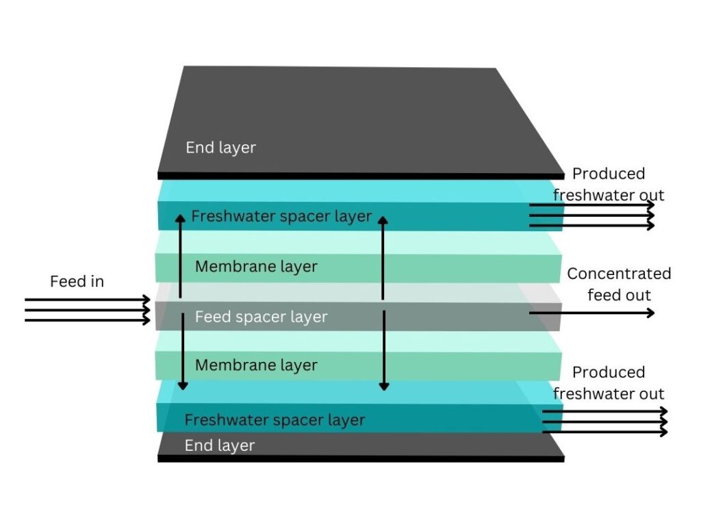
Structure of a typical reverse osmosis (RO) membrane, with fresh water going from the feed, through the membrane, to the freshwater spacer layer and out to the collection tube.
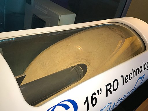
Cutaway of a typical 16″ reverse osmosis (RO) membrane. The spiral winding is visible in the centre around the tube.
Image by Z22, CC BY-SA 4.0 <https://creativecommons.org/licenses/by-sa/4.0>, via Wikimedia Commons
The physical transport of water through the membrane is different than just a sieve. A sieve filters based on size exclusion, simply blocking anything larger than its pores from coming across the sieve. When you bring this process to a very small scale, such as for RO membranes, the same laws of physics don’t always apply. The pores in the active layer of an RO membrane are so small that they transport individual water molecules across. This means that the larger scale dynamics of water, such as forming droplets and flowing, do not influence the membrane.
Active Layer Structure & Materials
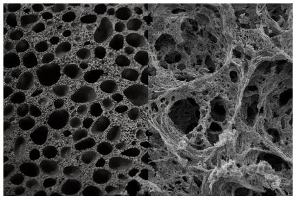
The structure of the active – polymer – layer of the membrane is simple but difficult to get right. The polymer that forms on the surface is not perfect and has small pores and larger pores. In some places, as with all polymer layers, there are larger areas called ‘defects’ at which the small strands of polymers do not form a perfect fit. These defects cause the transfer of pollutants such as salt ions and sometimes even suspended solids through the membrane.
The most common materials for the active layer are polyamides because of their relatively even distribution on the support layer, high salt rejection but also high water permeability, high resistance to pollutants (except chlorine), and compatibility with high pressures for long operation.
The active layer can be made thicker or of different materials to increase the salt rejection of the membrane. This also reduces the amount of water that comes through the membrane, called the permeability, because there are fewer and smaller pores in the active surface layer.
The Reverse Osmosis Process
The industrial process for drinking water production using RO membranes is straightforward, although there are several engineering challenges. The basics of the seawater to drinking water process are:
- First stage filtration for large solids >1mm or >150μm depending on the source water.
- Second stage filtration for smaller solids. Usually with polypropylene membranes or cartridges and down to 1-5μm.
- Chemical pretreatment which could be chlorination (Cl or NaOCl) followed by bisulfite (HSO3–) which deactivates the chlorine ions. Sometimes anti-biofouling agents are added to prevent biofilms (bacteria and slime) to form on the inside of the membranes.
- pH regulation, which is usually done by adding acid to limit the amount of carbonates that can form scale. As the membrane treatment removes pure water from the incoming stream, the dissolved salts in it such as calcium carbonate (CaCO₃) can precipitate (come out of solution) and form a layer on the membrane that limits the water flow.
- Addition of antiscalants, which prevents the formation of other types of scaling such as silica (SiO₂) and sulfite and fluoride salts scaling.
- Pumping: the water is now pressurised to around 80 bar (8 MPa / 1160 psi). This high pressure is needed to separate the water from the salt.
- The membrane stage, where the feed is concentrated (now called the concentrate), and the freshwater (called the permeate) are produced.
- pH adjustment where necessary, and remineralisation which is the step of adding minerals such as fluorides and calcium salts back to the water. This last step is done to ensure the water contains some ions which are required in the body. Common salts added are calcium chloride and magnesium salts.
- Disinfection. MOst produced water is not used immediately, so to reduce the growth of microoranisms like bacteria and parasites in the water, chlorine is often added. Another option is to bubble ozone through the water to kill any remaining bacteria and viruses and then store the water, although this does not provide longer lasting disinfection.
Engineering challenges
The very high pressures required for reverse osmosis are a challenge for the equipment used. The membranes can deal with these pressures, but they need to be placed in thick and heavy circular vessels – as can be seen in the image above.
Pumps and piping needs to be resistant to high pressures which is not much of a challenge, but it also cannot oxidise (rust) easily. This could contaminate the water with iron oxides and provide a space for bacteria to grow.
Pressure recovery is a technique used more often now than in the past. This technique reduces the total energy used by the system by recovering some of the pressure from the streams after the membrane. It uses a pressure exchanger, which is a device that has a high pressure inlet and low pressure inlet. There are small movable pistons in the pressure exchanger which pressurise the water on the low pressure side using the water on the high pressure side. Most often, a rotary device is used, a bit like a rotating machine gun. The rotation causes a constant exchange between the high and low pressure zones. A useful link to understand this concept better is through Wikipedia.
Equipment for Reverse Osmosis Processes
A significant part of system design is equipment selection. This is normally done by a team of project engineers with chemical and mechanical engineering backgrounds. Some key variables for the equipment selection for Reverse Osmosis plants are:
- Materials; salt water requires high grades steels such as stainless steel 316 or duplex, or inert materials such as plastics. High pressure requires thicker piping, but both plastic and stainless steel are used based on pressures, flowrates and budget.
- Power / electric; high pressure and high flowrate means that there will be large pumps with a significant electrical power load.
- Equipment lifetime; investments, future demand and water quality determine the minimum required lifetime of the plant.
Pumps
Besides the membranes, pumps are they key equipment that determine the performance of a Reverse Osmosis plant. Using very high power pumps can reduce the number of control system parts needed which makes control easier. This also makes spares more expensive and increases the risk to operation if a pump fails.
Much-used brands include Grundfos, Xylem, and Sulzer, amongst many others.
Membranes
Reverse Osmosis membranes are nearly always the same type: an active polyamide layer on top of a porous support layer usually made of polysulfone (PS) or polyethersulfone (PES). The chemistry of these membranes has been discussed above. These membranes are placed inside a robust membrane housing which is normally made of wound fibreglass and epoxy resin. Sometimes steel or machined metals are used, although these are more expensive.
To save cost on pressure vessels (housings), normally multiple membrane units are placed inside a long pressure vessel. Usually four to eight membrane elements are placed inside long housings to reduce the number of fittings and end caps used for the housing.
Commercially available membranes are produced by many manufacturers including Filmtec (part of DuPont), Lenntech, Toray, LG Chem, and Porex.
Pressure Exchangers
Pressure exchangers are a type of equipment used to transfer pressure energy from one stream to another. They operate by using many small chambers with a piston in the middle. First, low pressure liquid enters the chamber and pushes the piston to the other end. Then, high pressure liquid enters the same chamber from the other side, pushing the piston and with that pushing away the low pressure water, now at a higher pressure. To avoid pulsating motion, many small chambers are put in a cylindrical piece of equipment, that receives fluid one by one. Alternatively, larger pressure chambers with a single piston are used and a pulsation dampener is used to reduce its side effects.
Piping
Piping is a key part of RO plants, and as such is carefully designed to withstand high pressures – up to 80 bar / 1160 psi – and high flowrates. The most common piping for regular processes is stainless steel, but as these plants deal with high salinity water it is more prone to corrosion which can lead to cracks under high pressures. For this reason, polypropylene (PP) and cross-linked polyethylene (PEX) are common choices for RO piping. The material cost is lower than that of stainless steel, and these thermoplastics do not leech chemicals or rust into the water.
Valves
Valves are an important tool for process control and regulation, and need to withstand high pressures and salinity. Two types of valves are used for most control systems: on/off valves and control valves. On/off valves only open and shut, and are used to change flows between different parts of the system. These safety valves that open or close in the event of a high or low pressure, and can be manual valves but often they are controlled electronically or by air. Air controlled valves may also have a spring in them to open or close them instantly in the event of loss of air pressure, called a fail-safe valve.
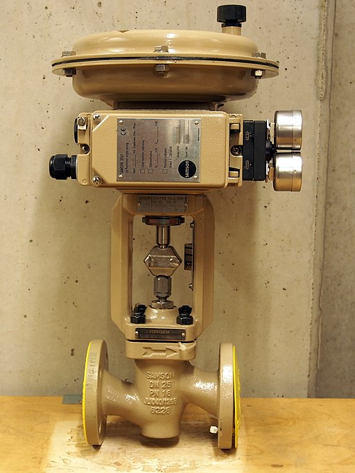
Control valves are a type of electronically controlled valve that regulate the flow of liquid through them. They are often linked to a flow meter just downstream of it, which is read by a controller. For electronically controlled valves, a servo (electric) motor is used that opens or closes the gate or ball of the valve incrementally. In air operated valves, a small air pressure regulator and a spring work together to provide a certain opening percentage of the valve.
Valves are often stainless steel due to its resistance to corrosion and pitting, although plastic on/off valves are common for certain systems. For RO systems, PVC valves are sometimes used although stainless steel is a safer option for most applications due to the high flow and pressure graduations it experiences.
Operating and Control Systems
Operating systems of RO plants are relatively simple: in essence a plant consists only of pumps, piping, valves, membranes, and a dosing system. Due to the high pressure of the system, many pumps are needed at different pressure levels and careful control is required to ensure process safety and equipment longevity. Additional systems that need control are the biocide and antiscalant dosing systems, pH dosing system, and filter backwash loops.
Most modern controllers are PID (proportional-integral-derivative) although PI (proportional-integral) controllers are also used, especially in older systems. The benefit of PI controllers is the simplicity of tuning, although PID controllers generally reach more steady flow rates which is beneficial for other equipment. Pump control can be done with variable speed drives (VSD) or variable frequency drives (VFD), and both are common based on the control system of the RO plant.
[…] The benefits of using RO for domestic water is that it removes dissolved salts as well as bacteria and viruses. For full details on Reverse Osmosis, check out this detailed scientific article about RO. […]